Burtons Academy Author
Joel Huey BA (Hons) – Content Editor
An electrocardiogram (ECG) provides non-invasive information on the heart’s electrical activity. Their use is becoming more common in everyday practice as they are often a standard module in newer multiparameter monitoring machines.
An ECG can be used during the entire anaesthesia process, including the pre-anaesthesia assessment, through to recovery, and in a diagnostic setting during conscious examinations.
Patients may be at risk of developing arrhythmias secondary to non-cardiac diseases, such as with:
- Particular disease processes e.g., gastric dilatation-volvulus
- Administration of anaesthesia drugs e.g., alpha-2 agonists
- The surgical procedure and technique e.g., splenectomy
- Electrolyte disturbances e.g., hyperkalaemia in a patient with urinary obstruction
- Myocardial ischaemia e.g., thromboembolic disease
Some arrhythmias may not require intervention, but some may require urgent attention as they could decrease cardiac output and subsequently cause organ-damaging hypotension. Arrhythmias can become life-threatening, like in a patient with sustained ventricular tachycardia that progresses to ventricular fibrillation.
In this blog, we discuss how an ECG is obtained and then outline the physics of an ECG machine to ensure you always get a trustworthy trace.
How electricity travels in the heart:
The muscle of the heart has two different types of cells:
- 1% of the cells are specialised nodal cells that can initiate and conduct impulses
- 99% of the cells are muscle cells that contract and conduct impulses (the myocardium)
A group of nodal cells are typically responsible for initiating the electrical impulse despite both types of cells in the heart being conductive. The sinoatrial (SA) node has the highest intrinsic rate and is responsible for setting the pace of the heart and is known as the pacemaker. The atrioventricular (AV) node is the other group of nodal cells.
The SA node is located in the top right of the atria and when it discharges, the depolarisation wave moves across both atrial muscles like a ripple effect. When the electrical impulse reaches the AV node near the bottom of the right atria, conduction passes into the ventricles via a narrow pathway called the bundle of His. The bundle of His runs down the ventricular septum and divides into two, forming the left and right bundle branches. At the bottom of the branches are fine Purkinje fibres that carry the impulse through the ventricular myocardium. A labelled diagram of the heart is shown in Figure 1.
It is this movement of the electrical impulse, or the changing action potential of the cells, which is detected by the ECG machine.
The movement of the electrical impulse produces 5 different waves (P, Q, R, S, T) which are grouped into 3 sections:
- The P wave represents atrial depolarisation
- The QRS complex represents ventricular depolarisation
- The T wave represents ventricular repolarisation. Atrial repolarisation is small and is normally hidden within the QRS complex.
Terminology:
It is just as important to use the right terminology when interpreting the waveforms and complexes as it is when identifying parts of the ECG machine:

- Electrocardiograph – the instrument used to record the electrocardiogram
- Electrocardiogram – the electrical waveform, known as the trace
- Electrode – attachments to connect the cables to the patient’s skin
- Cables – the wires that connect the ECG machine to the electrodes
- Lead – the direction that the electrical activity is read
- Voltage – potential difference between two points (the electrode attachments)
- Amplitude – the height of the waveform
- Hertz – the frequency of alternating electrical currents in cycles per second
Electrode Attachments
The cables attach to the patient via electrodes which are placed superficially on the surface or skin of the patient, detecting the changing action potential of the cardiac cells during depolarisation and repolarisation.
There are several types of electrode attachments, which are shown below in Table 1:
|
Crocodile clips
|
These clips ‘bite’ the skin and are often placed in the inguinal area or the axilla. The clips may have metal teeth, atraumatic soft-grip teeth, or a flat pad. It is important to bite as much of the skin as possible as this will spread the pressure load of the clip, reducing the discomfort to the patient, and maximising the contact made. A conducting media such as gel or spirit improves contact, as does shaving the area or parting the fur. Apply the gel between the clip before attaching it to the patient. |
|
Adhesive Pads |
These come in a variety of sizes with different attachments (pop on or banana plug). They can be placed on furless areas such as paw pads or the pinna and they can be taped in place to last the whole procedure. If the patient is dirty, the area may need to be cleaned or de-greased first. These pads usually contain silver/silver chloride and are unsuitable for use within an MRI machine, however, there are MRI compatible carbon-based pads that can be sourced. |
|
Limb plates
|
Limb plates are like Velcro bracelets that go around the distal limb of the patient and they come in one size, suitable for both cats and dogs. They are easy to apply without the need to clip fur as they have a large surface area. Gel should be used to improve contact and should be applied to the patient before attachment. These are well tolerated in conscious patients. |
|
Oesophageal ECG |
This is placed into the oesophagus under anaesthesia and inserted to a depth directly over the heart (approximately the 5th and 6th rib). The tip of the oesophageal electrode has a white wire (temperature sensor) and a green wire (positive electrode), the middle electrode has a black wire (reference), and the most cranial wire is the red (negative electrode). An oesophageal ECG is only capable of producing a Lead II trace. There has been one report of thermal burns occurring when used with a monopolar electrocautery unit due to an alternate pathway between the electrode and the grounding plate (Burgess et al., 2011). While many factors played into this unfortunate incident, we advise not to use the two pieces of equipment together. |
|
Hypodermic Needles |
Hypodermic needles (21-23g) are passed through the skin so crocodile clips can be attached. They are good for use in birds where other electrodes may not be suitable e.g., sticky pads. Care must be taken that the risk of needle stick injuries to staff and patients is minimised by using a rubber bung on the needle tip end. |


Different conductive mediums include:
- Surgical Spirit – this evaporates within 10-15 minutes
- Isopropyl alcohol – this has a longer contact time of 30-40 minutes
- Parker Signa Spray – this highly conductive spray lasts approximately an hour
- Gel – This provides long-term contact for 2+ hours. Gels include ultrasound gel, electrolyte gel and K-Y jelly. If gel is used on crocodile clips, they should be cleaned thoroughly after use to prevent surface corrosion.
Skin Resistance
To produce a good signal into the ECG machine, there should be as much input of the cardiac signal from the patient as possible, which is achieved by minimising as much resistance from the patient to the machine itself.
There are two resistances involved in the final signal that gets to the ECG machine, the skin resistance, and the input resistance of the machine:
- The skin resistance includes everything from the subcutaneous tissues, the skin, the electrodes, and the cable itself. Normally the skin resistance dominates, however, poor-quality attachments can start to impact this resistance e.g., rusty crocodile clips.
- There is an input resistance in the machine that is set by the manufacturer. It is usually 5 megaohms, but at a minimum, it must be 1 megaohm. If you are purchasing an ECG machine and have detailed specifications, then the higher the value, the more signal will get to the machine to be amplified and filtered into an ECG trace.
These two resistances create a formula which determines how much of the signal gets to the ECG machine and is shown in Figure 2:
Signal B = Signal A x input resistance ÷ (skin resistance + input resistance).

As you can see, if the resistance is zero, then 100% of the ECG signal reaches the machine. However, there is always some resistance to overcome as skin resistance usually is 100-400 Kiloohms.
For example:
- If the skin resistance is 400 kiloohms and the machine has an input resistance of 1 megaohm (which is 1000 kiloohms), then only 60% of the signal gets through:
- 400 kilohms ÷ 1000 kiloohms x 100% = 40% of signal is lost
- 400 kilohms ÷ 1000 kiloohms x 100% = 40% of signal is lost
- If the skin resistance is 100 kiloohms and the machine has an input resistance of 1 megaohm, then 90% of the signal gets through:
- 100 kilohms ÷ 1000 kiloohms x 100% = 10% of the signal is lost
As you can see, we are unable to change the input resistance of the ECG machine, however, we can minimise the amount of skin resistance between the patient and the electrodes. This can be achieved by using conductive gels, shaving, or wetting the fur, or by maximising the surface area in which the signal can be read (e.g., a bigger bite of the skin if using crocodile clips). Although the fur is wet or soaked, this still causes a barrier, just to a lesser degree. Using hypodermic needles will bypass some of the skin resistance, however, the surface area of the needle is very small.
The Machine
The ECG machine is essentially a voltmeter where a positive and negative electrode measures the biological potential difference of changing electrical activity in the heart.
When there is electrical activity, such as depolarisation, the waveforms are formed depending on which direction it is travelling in:
- If the electrical activity is moving towards the positive electrode, the waveform moves positively off the baseline.
- If the electrical activity is moving towards the negative electrode, the waveform moves negatively from the baseline.
- There is a flat baseline when there is no electrical activity e.g., between beats.
In Lead II where the negative electrode is on the patient’s right foreleg (see Figure 3) and the positive electrode is on the left hind leg:
- The positive P wave is formed as the impulse moves from the SA node towards the AV node, in the direction of the positive electrode.
- When the ventricular septum depolarises, there is a small amount of electricity that moves back up towards the atria and back towards the negative electrode, creating a small negative Q wave.
- The positive R wave is formed as the rest of the ventricular myocardium is depolarised, which is in the direction of the positive electrode.
- The negative S wave is formed as the top part of the ventricle is depolarised, where the impulse moves in the direction of the negative electrode.
- The T wave represents the repolarisation of the ventricles. The T wave can be positive, negative, or even biphasic (a mix of both).


The wave and complex morphology of a Lead II trace is shown in Figure 4.
The ECG machine can display the trace on a screen or printed on paper. A printed paper trace may be preferred by clinicians who are running diagnostic ECGs where measurements are taken of different wave amplitudes and durations. Some ECG machines have the functionality to export the trace data to software where measurements can be performed easily and then exported to the patient history or sent to a cardiologist. This functionality is in the Vital Monitor software. A strip refers to a section of the ECG trace that is analysed.
The trace can move at different speeds of 12.5mm/second, 25mm/second, and 50mm/second. The lower the trace speed, the more complexes are present on the strip however this may make the interpretation of waveforms and complexes difficult. Therefore, a speed of 25mm/second is often used for general monitoring and 50mm/second can be used in patients with a very fast heart rate.
The ECG machine has many components, such as the cables which have previously been mentioned. But it is important to understand how to use the cables correctly, as well as know what the ECG machine’s amplifier and channels do.
Cables

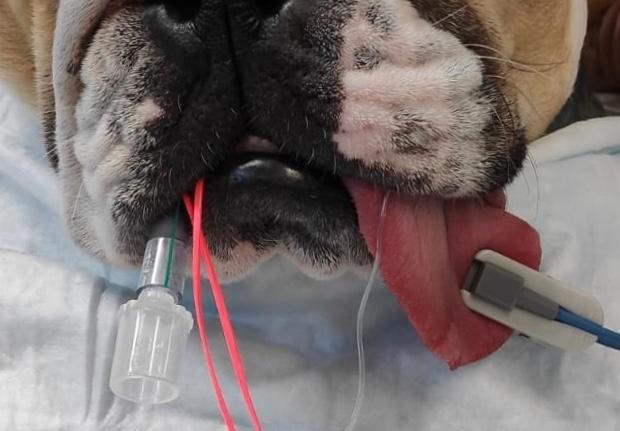
Cables have a different identifiable colour marker which corresponds to the placement location of the electrode attachment, as shown in Figure 5. In the UK, the cable colour and placement location are:
- Yellow – Left Fore
- Red – Right Fore
- Green – Left Hind
- Black – Right Hind
The cables may be shielded or unshielded and the quality of the ECG trace is impacted by this and their positioning around the patient.
Shielding:
If the cable is insulated then it is referred to as shielded, where an outer conductor is protecting the inner wire which is transmitting the electrical signal to the machine. A shielded cable reduces environmental interferences (such as the 50Hz mains interference) from being read by the ECG machine, therefore producing a high-quality signal and therefore trace.
After the yolk or split in the cabling, many ECG wires become unshielded, meaning they will be more susceptible to picking up mains interference and producing a poor-quality ECG trace. As it is difficult to identify if you have a machine that has unshielded cables or not, interference can be minimised by keeping the cables together when attached to the patient. This is because of Common Mode Rejection.
Common Mode Rejection:
For the ECG machine to read only the minor differences in cardiac potential to form the ECG trace, it must filter out identical noise inputs from both the positive and negative electrodes. To reject and filter out noise, all cables must ‘see’ the same interference. This is termed Common Mode Rejection (CMR) as the common mode of noise has been rejected, as shown in Figure 6. Conversely, if you hold just one lead from the ECG, the trace will go wild as the interference is not seen on the other cable and the machine thinks this is part of the differences in cardiac potential.

The cables can affect CMR if they have been arranged loosely and scattered around the patient as they are not ‘seeing’ the same path anymore. The ECG cables should be run close together and in a uniform arrangement so the ECG machine can cancel out any interference between them. This effect is shown below in Figure 7.

It is important to note that the reference for the ECG machine is the black cable (which attaches to the right hind electrode). If there is poor contact between this cable’s electrode and the patient, then there is no stable reference for the machine to subtract the noise from and the ECG signal will be unreadable.
Amplifier
Cellular voltage within the heart ranges from -90mV to +30mV, however when we try to measure this superficially with an ECG, only 0.5mV to 2mV of the signal reaches this skin. This is the small signal that the machine must amplify. An amplifier has two purposes:
- It filters interference from the ECG trace
- It is used to increase the amplitude of the electrical signal to be displayed or recorded
Other physiological and environmental interferences e.g., muscle activity or mains interference, must be eliminated from this signal so the small ECG signal can be identified. In addition to CMR, this is done with the use of different filters which narrows the frequency range that is picked up by the ECG machine.
There are different types of frequency settings that an ECG machine can be set to:
- Monitoring – This filter has a narrow bandwidth of 0.5-50Hz. This reduces distortion from muscle movement or mains etc and is commonly used in the general monitoring of anaesthesia. It may also be known as a low-pass filter. The Vetronic Lightning Multiparameter has a low pass filter of 35Hz, which reduces muscle interference.
- Surgery or Therapy – This filter has an even narrower bandwidth of 1-20Hz. This filter further reduces artefacts and interference, but QRS amplitude may be suppressed.
- Diagnostic - This wider bandwidth of 0.05-150Hz allows assessment of finer details of different waves and complexes, however, the signal may be susceptible to noise interference. A diagnostic filter can be used for monitoring, but a monitoring filter cannot be used for diagnostic purposes.
- ST – This filter has a bandwidth of 0.05-40Hz and is usually seen on an ECG designed for human medicine for the finer assessment of the ST segment.
You may see “notch on” or “notch off” on your ECG machine. This refers to a filter that rejects all noise around the 50Hz frequency, which is the mains interference.
Leads
Einthoven’s Triangle is a theoretical triangle over a patient’s body, with the heart in the middle. This equilateral triangle allows us to read the heart’s electrical activity along 3 different axes between two electrodes (bipolar configuration), giving us Leads I-III. The direction of Leads I-III is shown below in Figure 8. Of these, lead II is typically monitored under anaesthesia.

Depending on how many cables an ECG machine has, it may be able to read Lead I-III and 3 additional augmented unipolar leads. Although augmented leads are not commonly read in general practice, they are:
- aVR – the negative electrode is the combination of the LF and LH, and the RF becomes the positive electrode
- aVL – the negative electrode is the combination of the RF and LH, and the LF becomes the positive electrode
- aVF – the negative electrode is the combination of the RF and LF, and the LH becomes the positive electrode
|
Configuration |
Colours |
Leads |
Display/Channel |
|
3 Cables |
Red, green, yellow |
I, II, III |
One lead at a time |
|
3 Cables |
Red, green, black |
II only |
One lead at a time |
|
4 Cables |
Red, green, yellow, black |
I, II, III, aVR, aVL, aVF |
All leads simultaneously |
An ECG machine with a 3-cable configuration is termed a single lead machine as it only has two active electrodes at one time, meaning it can only display one Lead at a time. To view different Leads, you must scroll through the settings in the machine to change the channel. An ECG machine with a 4-cable configuration is referred to as a six-lead machine as all electrodes are active at one time and can therefore display up 6 Leads simultaneously.
Troubleshooting
Cables
If there is a problem suspected with the ECG cable or electrode, several tests can be performed, both before placement on the patient and once the ECG is attached. Please click on each test to be taken to our YouTube channel where these tests are being performed:
Double Counting
A multiparameter machine will display an ECG “heart rate” alongside the trace, however it may be seen to “double count” the actual pulse rate that is palpated or the heart rate that is auscultated.
Normally, the computer within the machine interprets a QRS complex as a beat except in some patients with large T wave amplitudes, it reads this as a QRS complex too as shown in Figure 9. This is one of the reasons the heart rate gained from the ECG may not be accurate.

Gain
Adjusting the gain of the ECG will increase or decrease the size of the trace on the screen. This feature can be useful to increase the ECG trace of a cat, which has small waveforms. A common error made is if the gain is set too high, which will make some of the waveforms look wide and ventricular, as shown below in Figure 10. Usually, the gain is set to 1cm/mV (10mm/mV).

Interference and Artefacts
It is important to be able to differentiate interference and artefacts on an ECG trace from that of true electrical activity in the heart. Interference and artefacts can erroneously produce waveforms that can mimic activity such as ventricular fibrillation or asystole, etc. The interference and artefacts may be electrical, or patient induced.
 Electrical interference usually occurs regularly and uniformly. This may be caused by the mains, electrical heat blankets, other monitoring equipment, mobile phones and even the person holding the patient. It can be reduced by using a notch filter, keeping the cables parallel to each other or by removing some of the local electrical equipment from the area (e.g., a fluid pump sitting on the table next to the patient). If there is too much mains interference when running a diagnostic ECG, it may be best to perform the recording while the ECG machine is using battery power. Another form of electrical interference is that of the electrosurgical unit, diathermy, which produces currents from >150Hz that cannot be eliminated from the ECG trace. This is shown in Figure 11.
Movement artefacts can be caused by a patient that is shivering or trembling as there will be the noise of neural origin however it is presented equally to all electrodes, so it is not cancelled out. It also looks different to the mains noise, which is regular and uniform. The differences are shown in Figure 12. Movement artefacts can be harder to eliminate, however, a muscle filter can be fitted to the ECG machine but will reduce the QRS complexes (R wave) as it stops frequencies that are <35Hz. To reduce the muscle activity interference, try positioning the electrodes on bony prominences or soothe the patient, letting them relax and get into a comfortable position.

Conclusion
Although ECG monitoring has become more common in everyday practice, understanding how to use the machine itself is just as important as being able to identify different complexes and waveforms. Some key points include:
- Improve skin contact with electrodes by dampening the fur and using electrode gel
- Keep cables together to improve CMR
- Ensure equipment is clean and maintained
References
Burgess, R., Freeman, L., Jennings, R., Lenz, S. (2011) "An Alternative Pathway Electrosurgical Unit Injury in a Dog", Veterinary Surgery, 40(4), 509-514.